Working at more than 5 bar groundwater pressure requires the use of a closed shield of the type hydro shield (slurry shield). In this environment, the success of the project depends on achieving a dynamic equilibrium between the external hydrostatic pressure, the fluid pressure inside the chamber and the pressure exerted by the slurry shield thrust. Throughout this article, based on Eurohinca's experience and recent international studies, we will review the physical principles, operational best practices and monitoring systems that allow this balance to be maintained.
Principle of operation of the hydro-shield
The hydro shield works with a bentonite fluid that fills the excavation chamber and recirculation circuits. The fluid transmits the pressure to the face, stabilizes the ground and transports the detritus to the separation plant located on the surface. The pressure in the chamber is modified by:
Sludge pumpingThe flow rate: changing the flow rate alters the column height and therefore the static pressure.
Regulation of discharge valves: opening or closing the bypass valve varies the back pressure.
Control of the rate of progressExcessive thrust causes overpressure; insufficient thrust allows water and material to enter.
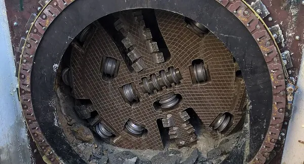
To review the complete anatomy of the equipment, please refer to the Closed shield - Hydroshield in our section of Equipment.
Previous hydrogeological characterization
Before you can set up the face pressure, it is essential to know:
Piezometric level and its seasonal oscillation.
Permeability coefficient (k) and formation compressibility.
Aquifer confinementUnconfined aquifers can relieve pressure via surface drainage; a confined aquifer can accumulate unexpected overpressure.
Our department of Technical assistance and engineering integrates these parameters into a numerical model that predicts the pressure required to maintain fronto-static equilibrium without inducing siphonage.
Calculation of face pressure (pf)
For saturated soils, the face pressure (pf) is defined as:
pf = γ-h + σ′ ± Δp
where γ is the specific gravity of the water, h the depth below the water table, σ′ the effective soil tension and Δp a safety factor. A well-tuned hydroshield works with Δp between +0.05 bar and +0.15 bar with respect to the local hydrostatic pressure. Exceeding this range can fracture the ground; falling short causes fluid losses and risk of flooding.
Best operating practices
Millimeter thrust control
The hydraulic thrust must accompany the rate of debris extraction. In the Infrastructure crossings of Valencia's railway ring, Eurohinca implemented a predictive control algorithm. The system adjusted the thrust every 0.5 seconds according to face pressure and mud flow rate. The result was an average deviation of ±0.03 bar from target during 320 m of advance in saturated sands.
4.2 Bentonite glue injection
As the shield advances, a hollow ring is created between the machine liner and the excavated ground. Inject a slurry of bentonite and cement into this area:
Seals leak paths for water.
Reduces pressure loss in the chamber.
Minimizes surface settlements, a key factor in Civil works urban.
Sealing systems in the segment crossing area
In tunneling with Tunnel of voussoirs a sealing brush and injection chamber is installed behind the cutter wheel. Keeping the pressure in that chamber 5 % above the face pressure prevents water from entering the finished tunnel.
Separation and recirculation circuit
The bentonite fluid returns to the separation plant where it is decanted, cleaned with hydrocyclones and reinjected. Controlling the density between 1.08 and 1.15 g/cm³ ensures the bearing capacity without overdensifying the sludge, something studied in depth at TBM excavation under high water pressure (2023) ResearchGate.
Real-time monitoring
A modern pressure management system combines:
Multipoint pressuresensors in the chamber, the unloading line and the segment passage area.
Magnetic flowmetersThey measure the input/output balance to detect leaks.
Piezometric gauges at surface: confirm that there are no overpressures causing outcrops.
Dashboards connected to the cloudintegrated in the platform of Excavation systems of Eurohinca.
In case the face pressure drops more than 0.1 bar in 10 s, the algorithm sends an alert and commands the PLC to reduce the feed rate and increase the mud flow rate.
When the external pressure exceeds 10 bar
Pressures greater than 10 bar (≈100 m water column) require:
Reinforced wheel structure with extra thickness and high yield strength steel.
Double O-ring system on all hydraulic connections.
Pressure hulls for intervention personnel.
From 12 bar upwards, some projects opt for Direct Pipewhich combines microtunnel shield with continuous pipe thrust, avoiding the operator chamber.
An emblematic case is the Durban (South Africa) subsea outfall, where hydrostatic pressure reached 13.5 bar. Engineers adopted a triple pump redundancy system and redesigned the wheel seals based on laboratory tests published in 2024 by the Institution of Engineers South Africa ascelibrary.org.
Recovery and restart after emergency stop
A shutdown of more than 30 minutes may cause water seepage into the chamber and pressure losses. The protocol recommends:
Close the bypass valve to isolate the chamber.
Re-inject mud until the target pressure is recovered.
Verify integrity of discharge line joints.
Start again with a slow advance (≤10 mm/min) for the first 2 m to stabilize the flow.
This procedure was applied in the system of Seawater harvesting systems for desalination of Gran Canaria, where a power outage caused a 22-minute stoppage without subsequent incidents.
Benefits of optimal pressure management
Security for the workforce and for the surface population.
Settlement reductionkey when working under railway lines or historic areas.
Sludge savings%: a fine-tuned circuit reduces bentonite consumption by about 18 %.
ProfitabilityAvoiding breaks and damaged seals means fewer stoppages and more meters excavated per shift.
Sustainabilityless fluid loss means less environmental impact, something valued in green finance programs applicable to Drainage works.
Conclusions
The pressure management under high groundwater with hydroshield is a discipline that combines geotechnics, hydraulics and mechanical control. A stable face pressure balance, supported by high-frequency sensors and an intelligent pumping and injection strategy, prevents seepage and settlement. Coupled with robust equipment design and safe shutdown protocols, it ensures sustained progress even below confined aquifers with more than 10 bar pressure.
If your next project involves crossings with risk of outcropping or submarine emissaries contact our team for an in-depth consultation. pressure management audit.